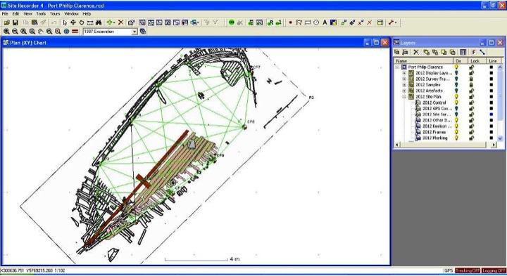
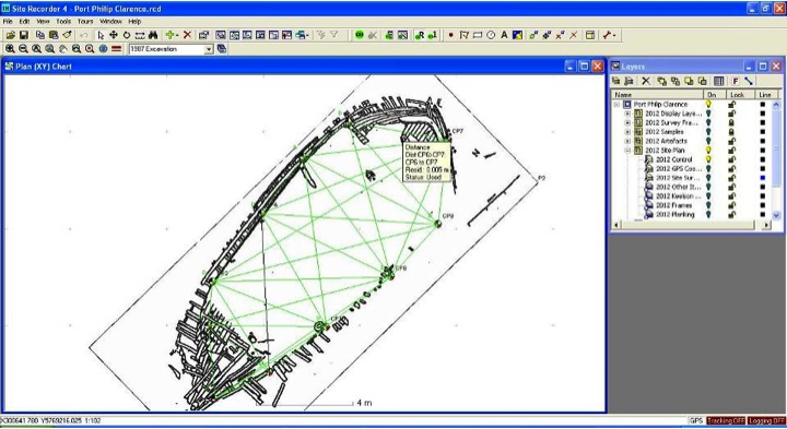
The Clarence team used 3H Consulting’s Site Recorder 4 (SR4) software to digitally map the trench during excavation.
SR4 allowed for the integration of data from different survey methods to generate the site plans. Survey data was directly managed by the software and did not require any pre-processing which is useful in limiting the number of processing steps to refine the data. This is often an issue when a processing work flow results in complex version control for intermediate data processing steps. All data validation was possible within the software itself.
The survey measurements on the site were primarily taken using Direct Survey Method (also referred to as 3D tri-lateration). This technique was selected as it negates the limitations of using baseline/offsets and plumbobs in sites with high vertical relief and strong current. While the starboard side of Clarence is relatively low relief, the current was up to 1.8 knots at times, and usually between 0.6 – 1 knot throughout the excavation.
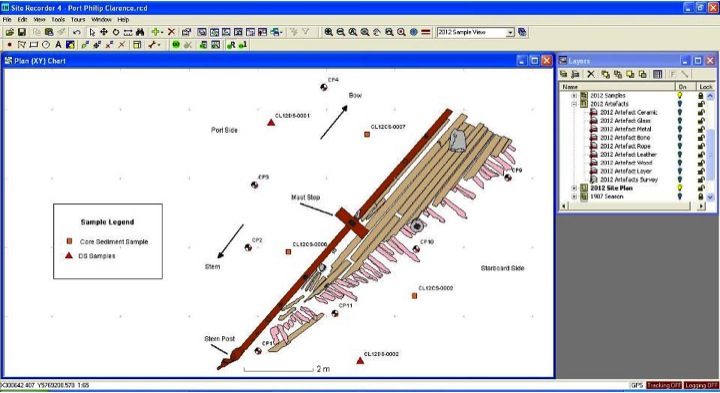
A network of 11 control points (or datums) were set up around the wreck site using star pickets. Once installed, tide-adjusted depth measurements were acquired and distances between each datum and at least 5 other datums were taken. Once the network was set up it was possible to accurately measure points inside and around the wreck. Each recording required measurements to at least 3 datums and a tide-adjusted depth measurement. Measurements were then transferred into the Site recorder program for processing.
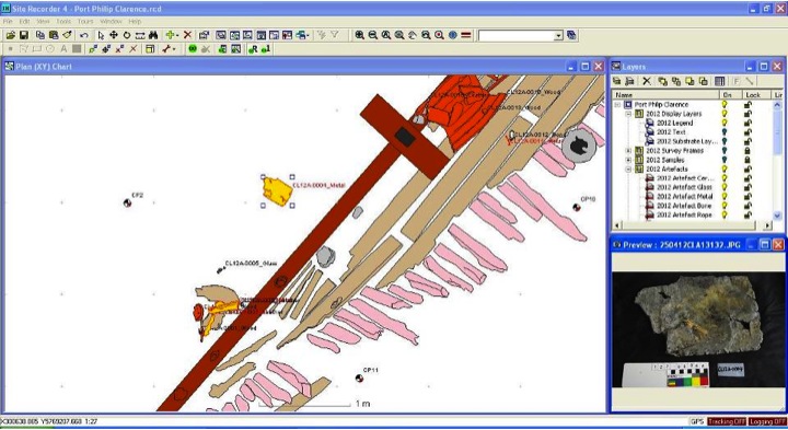
The 2D site plans for the excavation trench was assembled using data from a range of survey techniques, including direct survey method, feature measurements, drawing frames, and scaled and rectified photography. These plans can be viewed in the gallery below as static JPEG images; SR4 files will be uploaded soon and will be viewable using the demonstration mode of Site Recorder 4.
At least one point on an artefact was surveyed in and the artefact photographed in situ to establish its orientation. In situ photos were also used to create digitized line drawings of the artefacts and added to artefact data layers. This allowed for all artefacts to be scaled, aligned and accurately positioned within the site plan.
The structural site plan, sample layers, and artefact layers are integrated within SR4 and can be selectively made editable or visible within the system.
Data processing and text on SR4 supplied by project researcher Amer Khan.
-
- 2012 excavation trench shown with artefacts and image preview
-
- 2012 sample layers overlayed on plan of 2012 excavation trench
-
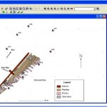
- 2012 site plan showing datum points

-
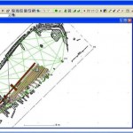
- Control point network layer with 2012 excavation and 1987 site plan
-
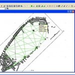
- 1987 site plan with datum network overlay
-
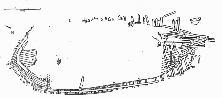
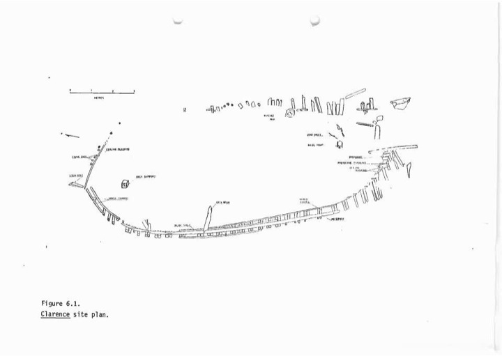
- 1987 Clarence site plan
-
- 1985 Clarence site plan
-
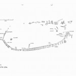
- Geo-referenced 1987 site plan of Clarence


")


